
Quick and dirty Lithium battery-powered Wemos D1 Mini
The Wemos D1 Mini is an ESP8266 based prototyping board with WiFi connectivity and countless applications. It becomes even more useful in battery-powered applications, where with the proper setup, it can run low-powered for months at a time — or only hours if done incorrectly.
This is the quick and dirty guide to running a Wemos D1 Mini powered by Lithium-Ion batteries: We will be blatantly ignoring several design specifications, so double check everything before using in a critical project. Several things will vary, and since there is plenty of clones of the board some boards will work better than others.
Warning: Lithium-Ion batteries always command healthy respect, due to the energy they store! Do not use bad cells, and do not leave batteries unattended in places where a fire can develop, especially while charging. That being said, the setup given here should be as safe as most other Lithium-Ion battery projects.
Why run off a battery?
You chose a Wemos D1 because you want to do some WiFi connectivity. This narrows down the useful modes from the overwhelming large table of possibilities. The approach will be slightly different depending on why you want to run off a battery. There are 3 main usecases:
- Periodically wake up on a timer, do some work, connect to WiFi, and go back to sleep. Here we can utilize the deep sleep mode of the ESP8266, and get lifetimes in months.
- Wake up based on an external pin trigger, do some work, connect to WiFi, and go back to sleep. Here we can also utilize deep sleep, and get lifetimes in weeks/months.
- React with low latency to an external pin, do some work, and go to sleep while still connected to WiFi. Here we can utilize light sleep, but only get lifetimes in hours/days.
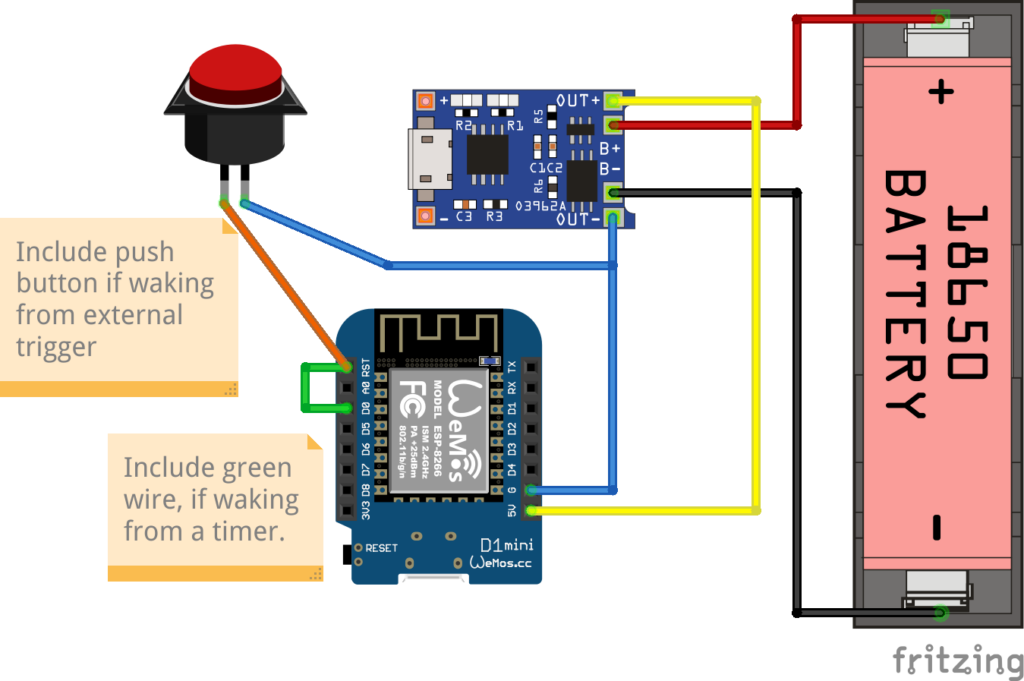
Hardware setup
The hardware needed is:
- Wemos D1 Mini
- TP4056 module with “discharge protection”, most modules with more than one chip has this, but be careful!
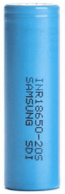
- Lithium-Ion battery, e.g. a 18650 cell, and probably a holder for the battery
What you don’t want is anything resembling a power bank or battery shield with a regulated output (5V or 3V). These are practically useless, simply a more expensive battery holder! Two reasons: poorly built (I have several where standby is prevented by pulling 100 mA through a resistor!), and you don’t want a switching mode power supply. The keyword here is “quiescent current”: an SMPS can easily consume 5-10 mA continuously, which could very likely be the majority of the current draw.
Waking on a timer – deep sleep
Full code example for deep sleeping on a timer.
To start deep sleep for a specified period of time:
//Sleep for some time; when waking everything will be reset and setup() will run again
ESP.deepSleep(30 * MICROSECONDS_PER_SEC);
Note that you can’t safely sleep for more than approximately 3 hours. Power usage is approx 0.3–0.4mA when deep sleeping.
Keep in mind that after waking from the timer the chip will be reset, meaning no state is available, and WiFi will have to reconnect. Reconnecting to WiFi can be anything from 3–10 seconds or even longer, meaning that will be a delay before the program can resume.
Waking on an pin trigger (reset)
Full code example for deep sleeping waiting for a pin trigger.
The code is exactly the same as waking on a timer, with one exception:
//Sleep until RESET pin is triggered
ESP.deepSleep(0);
The chip will be effectively Cinderella’ed, sleeping until a RESET is triggered. Same caveats apply: waking up the program is restarted, and reconnecting to WiFi will be a delay.
Stay connected – low latency
Full code example for light sleeping connected to WiFi waiting for a pin trigger. Note that the button should be connected to D3 for this example, not RST.
The key parts are:
void setup() {
  ...
  WiFi.setSleepMode(WIFI_LIGHT_SLEEP, 3);  // Automatic Light Sleep
}

void loop() {
  ...
  delay(350); // Any value between 100--500 will work, higher value more power savings
    // but also slower wakeup!
}
Simply delaying will bring power savings — simple and easy!
When awake power consumption is around 75mA. Average power consumption when light sleeping with delay(200) is around 45 mA, with delay(350) and larger is around 30–40mA.
Measuring battery depletion
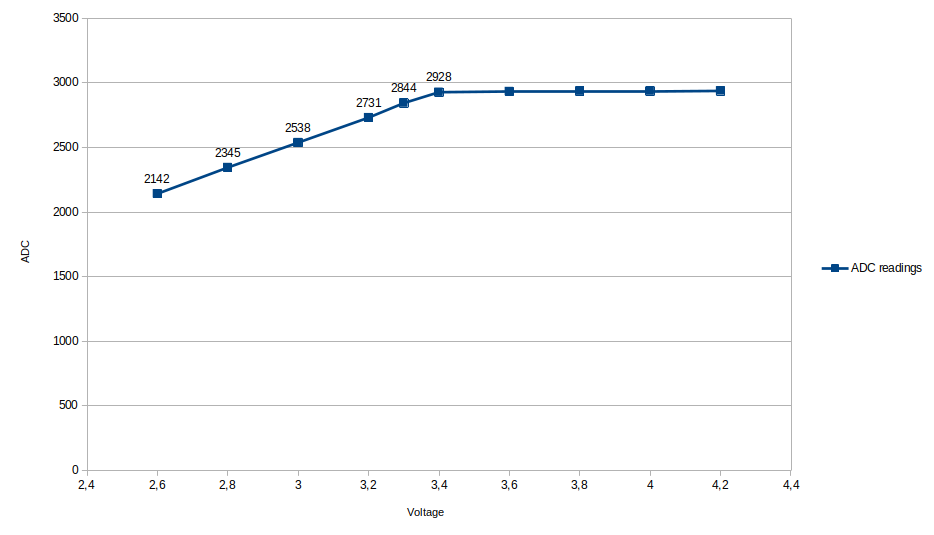
The ESP can measure it’s internal VCC supply voltage, and because the battery will start dropping below the rated 3.3V before it is depleted, this allows to get an warning when the battery starts to deplete.
ADC_MODE(ADC_VCC);

void loop() {
  if (ESP.getVcc() < 2800) {
    //Do something to warn of low battery
  }
}
In my experience the Vcc reading will drop below 2800 when the battery starts to be depleted.
Note that measuring the VCC while connected with USB is not possible, as the USB connection will pull up the battery and the 5V rail to 5V!
Calculating battery life
Here is a quick calculator for how long your Wemos D1 Mini can stay powered
Deep sleep
(conservatively assumes base load 1mA, 10 secs burst of 100mA for every wakeup), resulting in
–
Light sleep
–
Of course the consumption can be brought even lower: some chips are unused but partly connected and will have some leakage (LEDs, USB chip on the Wemos). Making it even leaner is outside the scope of quick and dirty.


")


15 dec
0 Comments