
Measuring high DC supply voltage with an Arduino
For my home-monitoring setup I would like an Arduino to measure the supply voltage it is getting from a DC battery UPS (Uninteruptible Power Supply). Unfortunately (actually by design, but that’s another story), the power supply is 24V, which means it will put out anywhere from 21.3V-29.8V (according to the manufacturer), which is far too much to measure with the Arduino’s 0-5V input range. For simplicity’s sake, lets assume we want to measure a 20-30V voltage.
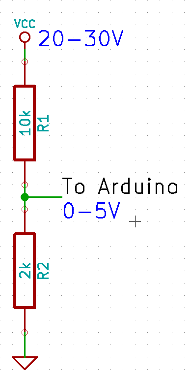
The immediate answer is to use a voltage divider, which will bring a voltage in the 0-30V range into the 0-5V range. The general formula for the resistor divider is:
 to give
  , so
, so
 Now, just as a sanity check we should calculate the current of the resistor divider, to make sure we’re not converting too much electricity into heat. Ohm’s law gives us
 over the range.
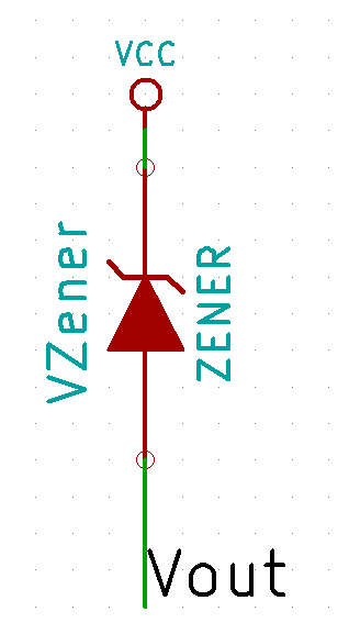
If only we could move the lower bound, so that 20V would map to 0V on the Arduino. A wild Zener Diode appears! One use of a Zener diode is as a voltage shifter.
over the range.
If only we could move the lower bound, so that 20V would map to 0V on the Arduino. A wild Zener Diode appears! One use of a Zener diode is as a voltage shifter.

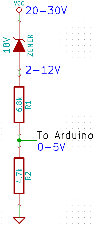
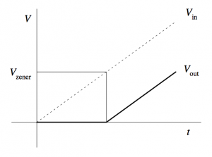 The closest Zener diode I could find was an 18V of the BZX79 series. This resulted in the following circuit:
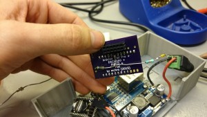
 which I hacked into my Arduino box.
 Now, theoretically the formula for translating an voltage at the Arduino to the supply voltage should be:
Plot it into a spreadsheet, create a graph and add a linear regression gives:
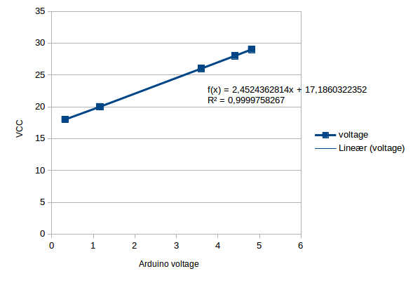 Now, this formula is a bit different compared to the theoretical one, mainly in the Zener diode drop. However, the datasheet for the BZX79 actually has the 18V C-type (
 ) as between 16.8-19.1V, so this is well within spec. Since this is just a one-off, I’m happy to just use the measured formula, as this will be more accurate.
The final precision should be
) as between 16.8-19.1V, so this is well within spec. Since this is just a one-off, I’m happy to just use the measured formula, as this will be more accurate.
The final precision should be  . The current should be around
  , which again is ok.
![\[V_{out} = \frac{R_2}{R_1+R_2} \cdot V_{in}\]](http://blog.smartere.dk/wp-content/ql-cache/quicklatex.com-ee1f44dbd85a1cd2218265ee49ce5255_l3.png "Rendered by QuickLaTeX.com")
to give , so
![\[\frac{5}{30} = \frac{R_2}{R_1+R_2}\]](http://blog.smartere.dk/wp-content/ql-cache/quicklatex.com-f02f447533b604db627794c4ebd6140b_l3.png "Rendered by QuickLaTeX.com")
 Now, just as a sanity check we should calculate the current of the resistor divider, to make sure we’re not converting too much electricity into heat. Ohm’s law gives us
![\[ I = \frac{U}{R}\]](http://blog.smartere.dk/wp-content/ql-cache/quicklatex.com-93017fbe68496cbd35e880ea8ee1c4b5_l3.png "Rendered by QuickLaTeX.com")
![\[ I = \frac{30}{12000} = 0.0025 A = 2.5 mA\]](http://blog.smartere.dk/wp-content/ql-cache/quicklatex.com-6631b393a242838c08feb147241b12dd_l3.png "Rendered by QuickLaTeX.com")
over the range.
If only we could move the lower bound, so that 20V would map to 0V on the Arduino. A wild Zener Diode appears! One use of a Zener diode is as a voltage shifter.
 The closest Zener diode I could find was an 18V of the BZX79 series. This resulted in the following circuit:
 which I hacked into my Arduino box.
 Now, theoretically the formula for translating an voltage at the Arduino to the supply voltage should be:
![\[Vcc = V_{in} / (4700/(4700+6800)) + 18 = V_{in} \cdot 2.4468 + 18\]](http://blog.smartere.dk/wp-content/ql-cache/quicklatex.com-2bf301ad44061de9fd4492ef666f33ad_l3.png "Rendered by QuickLaTeX.com")
| Input voltage | Arduino pin |
| 18V | 0.32V |
| 20V | 1.16V |
| 26V | 3.60V |
| 28V | 4.41V |
| 29V | 4.81V |
Now, this formula is a bit different compared to the theoretical one, mainly in the Zener diode drop. However, the datasheet for the BZX79 actually has the 18V C-type () as between 16.8-19.1V, so this is well within spec. Since this is just a one-off, I’m happy to just use the measured formula, as this will be more accurate.
The final precision should be . The current should be around , which again is ok. 


31 aug
0 Comments