
Ford 3000 Tractor Instrument Voltage Stabilizer – Mechanical PWM!
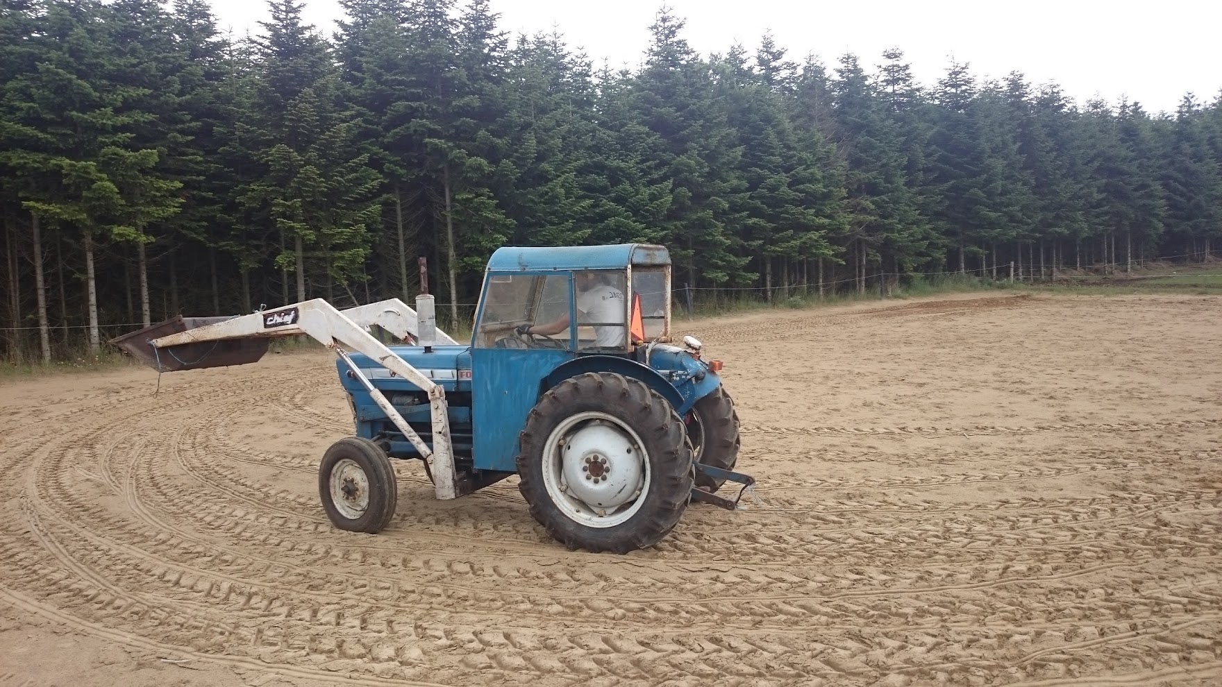
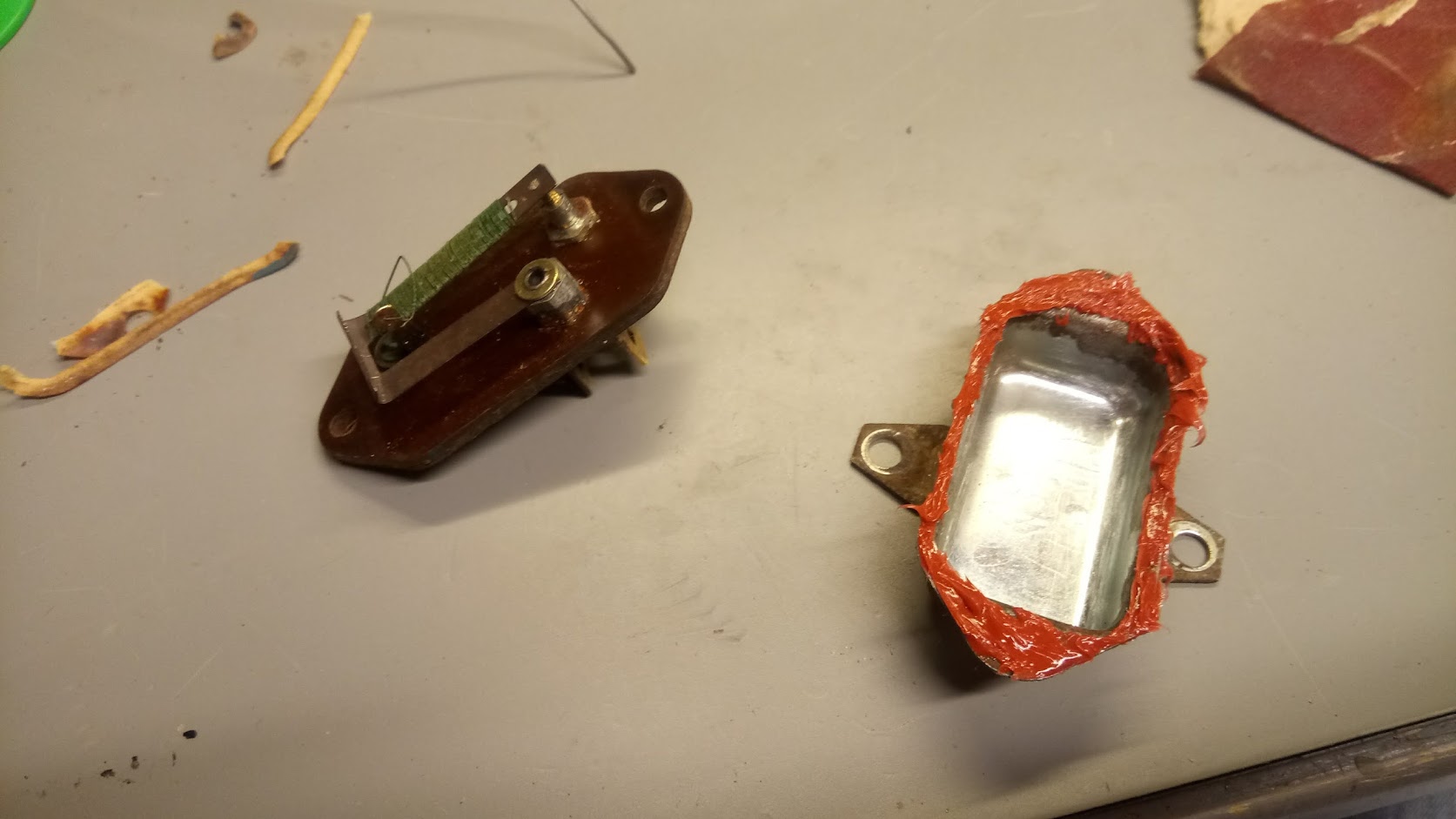
Some time ago we bought a nice used Ford 3000 tractor (3 cylinder diesel, Chief frontloader). It needed some work, and one of the items was a new wiring harness. After replacing all the wiring everything seemed to work fine, until one day all the instruments just died; this being a mechanical beast everything else kept working. After quite some investigation, I found out that the instrument fuse (the only fuse in the entire system) had blown. Replacing it just blew it again, so something was clearly wrong. This lead to taking out the so-called “instrument voltage stabilizer”, and disassembling it.
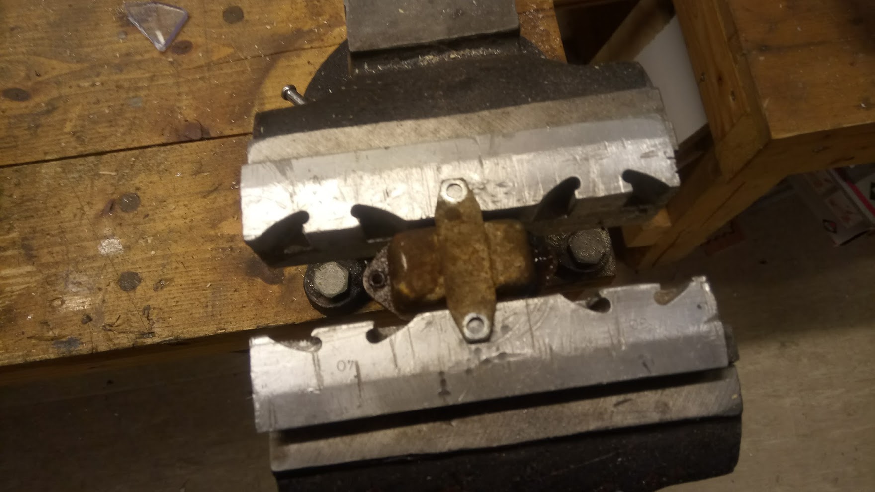
Apparently I had connected it in such a way that the arm had raised itself, and was now short-circuiting to the case. I had already ordered a replacement, but only got what was essentially a very expensive connection:

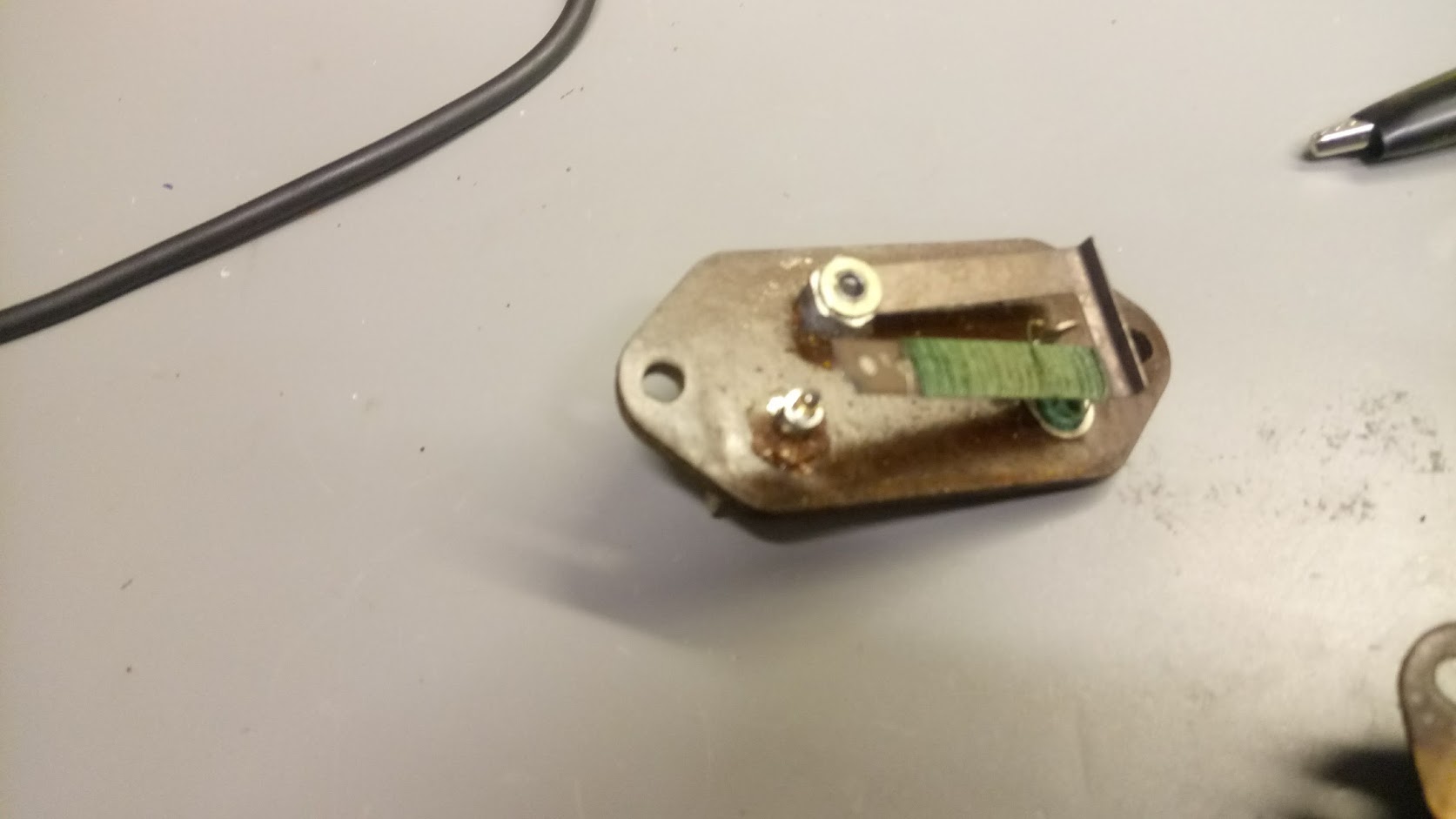
So, what was the mechanism actually doing, and is it essential? After some headscratching at Hal9k the conclusion was that it was essentially a mechanical PWM, with something like this diagram
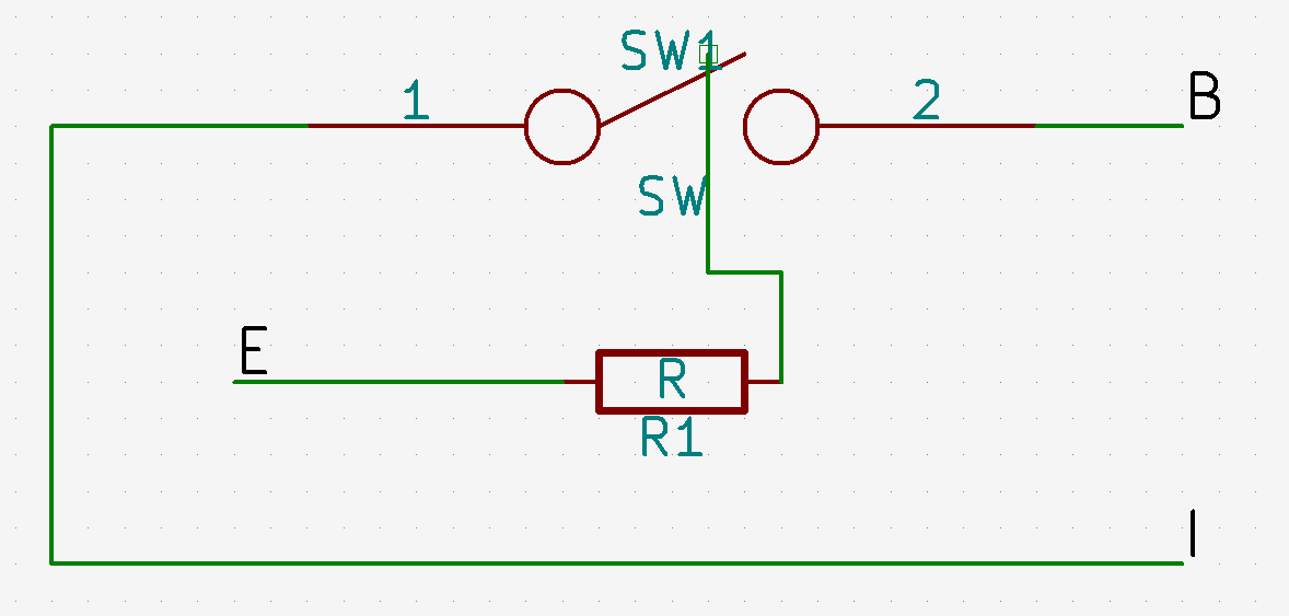
When the switch is touching the terminal current is flowing from the battery (B) to the instruments (I), but also to ground (E) through the resistor wrapped around the switch arm, causing the metal in the switch to heat up and lift. This breaks the connection, whereafter the switch cools down, and at some point makes contact again. Beautifully simple mechanism! Bending the arm back into position essentially fixed the device, and gave this waveform
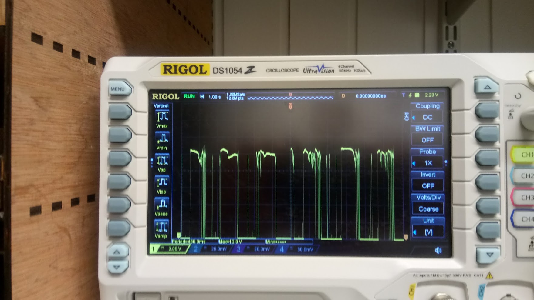
I have seen the function described online as “pulsating DC”, which is actually quite accurate. So, I re-assembled the stabilizer with some sealant, inserted in the instrument cluster of the tractor, and it has worked perfectly ever since.
The only question is why it is done this way, if just giving a constant DC voltage from the battery also seems to work? I haven’t looked into it further, but my best guess is that the instruments are using coils to move the dials slowly, and that the PWM will heat up the coils less. In conclusion: If your voltage “stabilizer” is broken, you can probably do without it, or quite easily repair it.
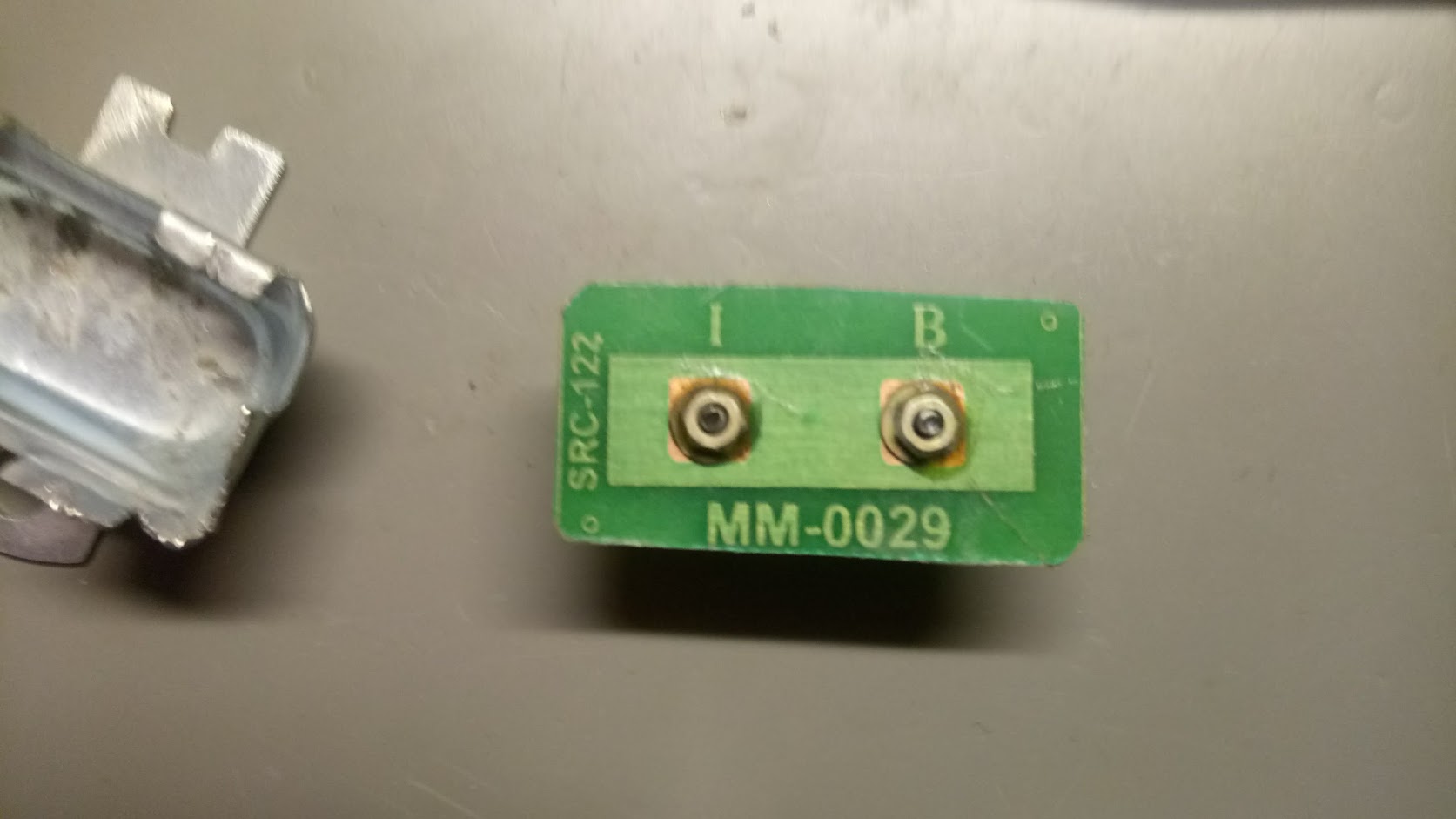
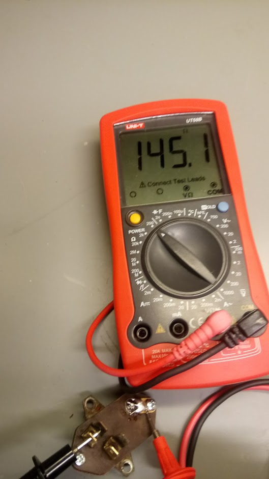
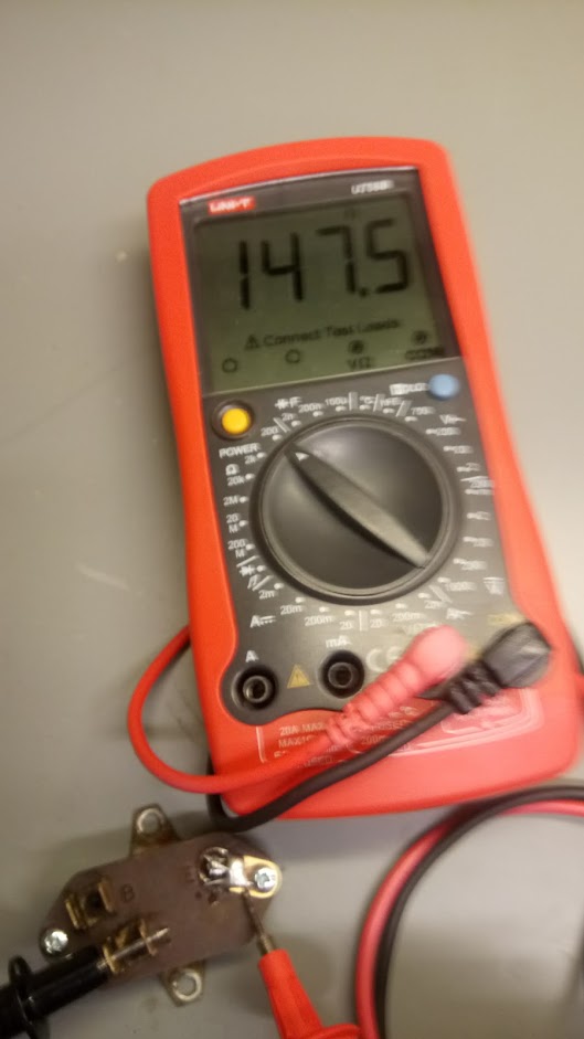
For reference, here are the resistance readings between B-E, and I-E:
![\[V_{out} = \frac{R_2}{R_1+R_2} \cdot V_{in}\]](http://blog.smartere.dk/wp-content/ql-cache/quicklatex.com-ee1f44dbd85a1cd2218265ee49ce5255_l3.png "Rendered by QuickLaTeX.com")
 to give
  , so
, so
![\[\frac{5}{30} = \frac{R_2}{R_1+R_2}\]](http://blog.smartere.dk/wp-content/ql-cache/quicklatex.com-f02f447533b604db627794c4ebd6140b_l3.png "Rendered by QuickLaTeX.com")
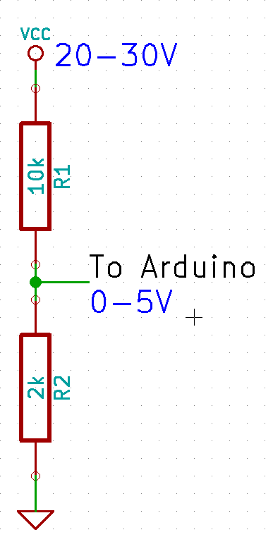
![\[ I = \frac{U}{R}\]](http://blog.smartere.dk/wp-content/ql-cache/quicklatex.com-93017fbe68496cbd35e880ea8ee1c4b5_l3.png "Rendered by QuickLaTeX.com")
![\[ I = \frac{30}{12000} = 0.0025 A = 2.5 mA\]](http://blog.smartere.dk/wp-content/ql-cache/quicklatex.com-6631b393a242838c08feb147241b12dd_l3.png "Rendered by QuickLaTeX.com")
 over the range.
If only we could move the lower bound, so that 20V would map to 0V on the Arduino. A wild
over the range.
If only we could move the lower bound, so that 20V would map to 0V on the Arduino. A wild 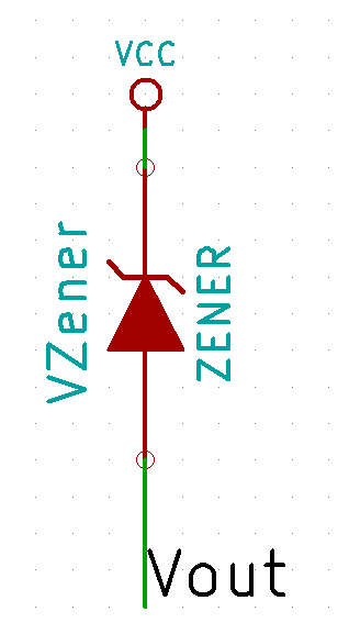
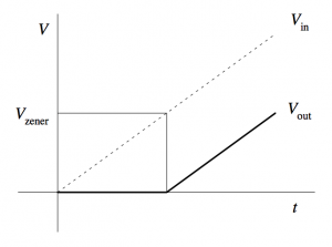 The closest Zener diode I could find was an 18V of the
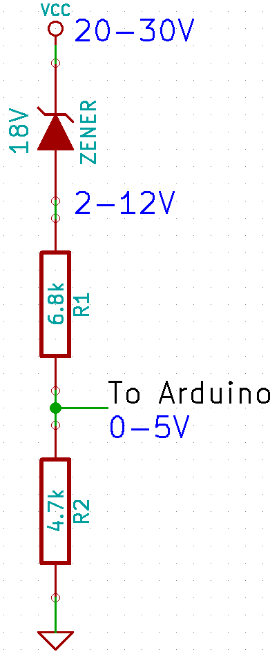
![\[Vcc = V_{in} / (4700/(4700+6800)) + 18 = V_{in} \cdot 2.4468 + 18\]](http://blog.smartere.dk/wp-content/ql-cache/quicklatex.com-2bf301ad44061de9fd4492ef666f33ad_l3.png "Rendered by QuickLaTeX.com")
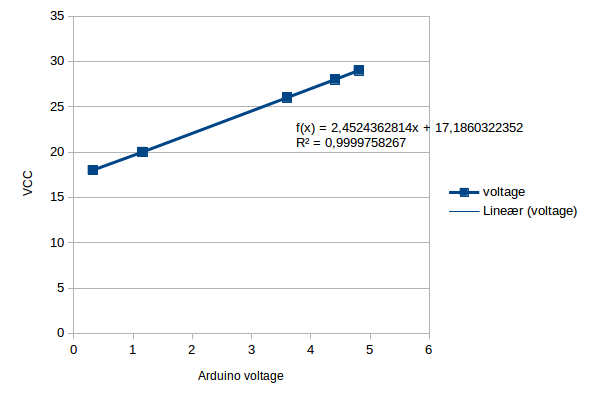
 ) as between 16.8-19.1V, so this is well within spec. Since this is just a one-off, I’m happy to just use the measured formula, as this will be more accurate.
The final precision should be
) as between 16.8-19.1V, so this is well within spec. Since this is just a one-off, I’m happy to just use the measured formula, as this will be more accurate.
The final precision should be  . The current should be around
  , which again is ok.


25 maj
0 Comments